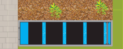
ERIC in running operation
The pure simplicity of the box itself understates the importance of what is contained inside the box and these are all detailed on the next page. This page outlines the box itself and why the need for total simplicity is of great importance to the operation.
Below are plan/section drawings with dimensions of the ERIC FOUR unit, all other standard units are detailed later.
All ERIC units require a flat base which can be produced by any of these methods but they also need perfectly vertical walls fitted to the flat base which produces problems in that all these earlier production methods considered require ‘draw angles’ in order to allow the finished carcasses to be removed from the mouldings. Furthermore, despite the narrow internal width and the shallow depth shown, unless the mouldings are produced with excessively thick walls they still require additional support due to the length required otherwise ‘bowing’ would take place to produce distortion of the perfectly straight walls.
To produce a simple flat-bottomed box of these dimensions with perfectly simple vertical walls that will retain perfect shape when filled with water is not exactly as simple as I discovered!
In view of this, and after several trials, I chose 9mm flat polypropylene sheet material to form the box internals. Whilst this material is almost indestructible for outdoors situations in all temperatures (unlike very brittle UPVC in colder temperatures) it still distorts slightly if formed in this sheet thickness only. The cost of forming the units in 30mm thick polypropylene proved both to be far too expensive and heavy – hence the angle and box section steel support frames that produce the perfect finished box. There is also a real ‘elasticity’ to the polypropylene material, which makes it pliable to a degree and also the comforting fact that there is nothing that will attach to the surfaces of the material in fishpond usage by way of algae.
This material is used in production lines, laboratories and food outlets where hygiene has great importance, it is completely inert and shrugs off all forms of bacteria. Whilst it is a superb material for fishpond filtration usage it also has a cost downside whereby the only material that can be welded to it is polypropylene itself. There are no glues/solvents that can be used and so the polypropylene fittings shown are very expensive to purchase and fuse-weld into place. The good news is, that by using this construction method for the box, I am not tied to any size restrictions produced by having to pay for very expensive mould tools or formers and therefore this allows me to tailor-make the boxes and insert the position of fittings for individual requirements at no extra cost.
All units have one single 4” (110mm) connection from the pond bottom drain and this is fitted centrally as shown. The other connection next to this is the 4” (110mm) which takes discharged water and overflow water to sewer – this can be positioned to the left or right of the central fitting with each specific order to give unhindered connection to waste. Each unit comes with a 4” (110mm) thick wall polypropylene ‘O’ ring standpipe fitted with a pull handle.
The perforated wall dividing the smaller prime mechanical stage from the longer biological stage can be seen in the drawings and the total measurements of the apertures exceed the diameter of the incoming 4″ diameter line from the bottom drain, hence no real restrictions in flow are possible under the required flow rates, in short, it can never block as such.
There is a 1.5” (50mm) male threaded nipple fuse-welded into the exit of the end wall for male screw connection to fit on a flap valve or the externally mounted water pump, which will generally be the most popular choice.
That’s about all there is to the box itself apart from the large bore, heavy duty 3/8” aeration assembly which is concealed and protected below the angle section of the steel box as shown. This 3/8” line is connected directly to the air pump that powers the aeration to each box.
Siting of all ERIC unit/s is also very simple if one bears in mind again that these are all gravity-fed systems and water levels in the filter units are determined by the finished pond water level itself. Again, this is unique to each individual pond but if one marks a point on the inside of the filter wall 1” (25mm) below the top of the box then this is perfect to show final water maximum level before any water pumps are operated. (At this standing level, the box contents will be slightly submerged but once the system is started the water level in the box will drop slightly to show the top surfaces of the contents at perfect running level.)
No very costly retaining walls around the unit are required and nor are any ladders required with available room to be able to climb down in order to access and operate any control valves when carrying out normal discharge requirements.
By lifting the standpipe from the discharge socket and slowly placing it to completely block off the pond via the bottom drain, water will exit the mechanical stage and disappear into the open sewer line. After 26 seconds ONLY the entire unit is discharged to waste, replace the standpipe to its normal position and that’s all that is required on a daily basis.
There is a built-in system overflow in the standpipe of all ERIC units that can be simply drilled once the running level of each system has been determined after the system pump has been operated for the first time. There is also an in-built drain-line purge assembly whereby the purged water can be taken directly to waste instead of being directed into the mechanical stage.
So that’s about all that is necessary to give details of the box itself.


