Another 2010 pond installation from start to finish.
The system described here that will be covered from start to finish has been on the cards for some time now. The outline plans were designed and completed in late summer 2009 but, for a mixture of reasons all outside the control of the client concerned, the actual work could not proceed until May 2010. The filtration system for this design will be by way of six Eric Four units supplied by way of three Eric Twin Four systems.
BACKGROUND
This design is another prime example as to why I have always said every pond is unique. For starters the pond is a perfect circle and is the only shape that can possibly compliment the surroundings of this system perfectly. Reasons for saying this is that it is to be installed in the large entrance courtyard of a traditional, listed country estate in the UK and any other shape would simply look out of place.
As to the shape itself, I have often mentioned that, in terms of efficiency, a perfect circle is the best possible pond shape for any Koi pond – simply because of the possibilities of perfect base performance and perfect current return patterns that can be produced and achieved if designed and installed correctly. For the Koi that will be introduced to the system on completion it should be the best possible environment for them to grow in perfect shape and health. However, I have also mentioned before that a perfect circle can appear to look visually ‘boring’ in most surroundings but this particular situation is doubtless the exception.
The pond itself will be, for the most part, an in-ground design but will finish above ground level. It will be installed somewhat centrally in the large courtyard area where visitors can walk around the entire pond freely or sit on the pond walls to enjoy the Koi. Visually it will look very much like the traditional English stately home water features used in the past by the likes of Capability Brown complete with the desired central fountain there for all to see. The difference is that this will be a purpose-built Koi pond and not a shallow unfiltered water feature as in days of old.
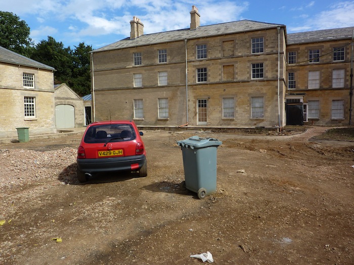
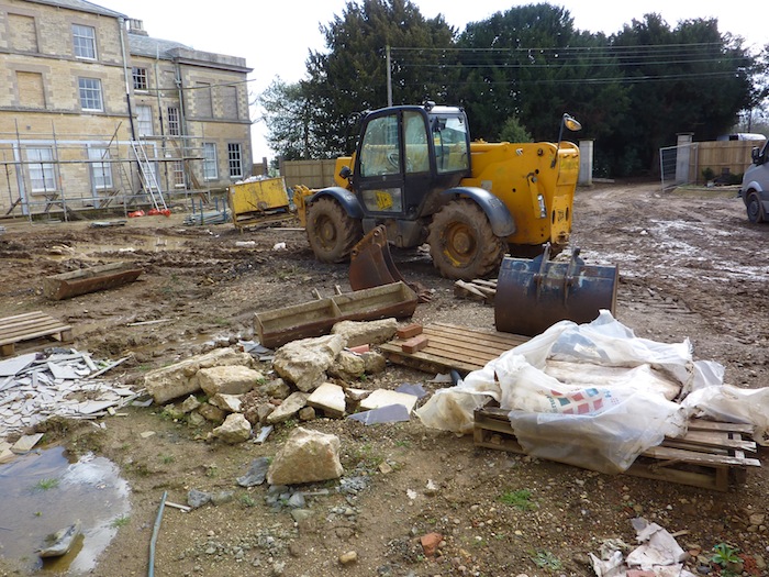
This shows the main residence in the background, the entrance into the courtyard is on the right of the shot.
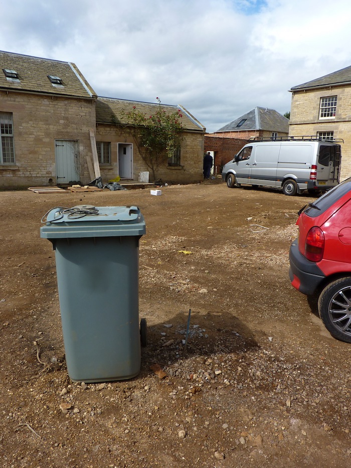
The pond itself will be positioned near where the car can be seen and the filtration system and equipment will be concealed some 25 metres distant from the pond to the left of the shot as shown on the next shot.
The person standing near the van shows where the filtration and equipment housing will be concealed from view.
The internal dimension of the finished pond will be 8 metres diameter and will have a depth at the centre of 2.25 metres. This will result in a pond water volume of some 23,500 gallons or 107,000 litres.
In the case of a perfectly circular pond, there is only one choice as to where to position the pond drain/s and that is dead centre. This case is no exception other than the fact that a standard bottom drain is nowhere near man enough to handle this particular pond volume.
In order to ensure we have the vital ‘one drain to one filter to one pump principle’ on this particular system we need to design and produce a bottom drain that can handle the flow rate required and, at the same time, produce the perfect base vacuum requirements.
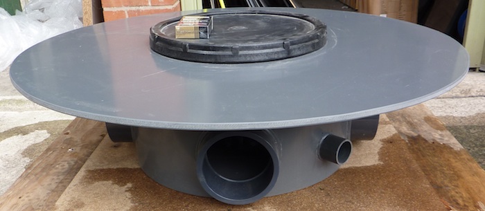
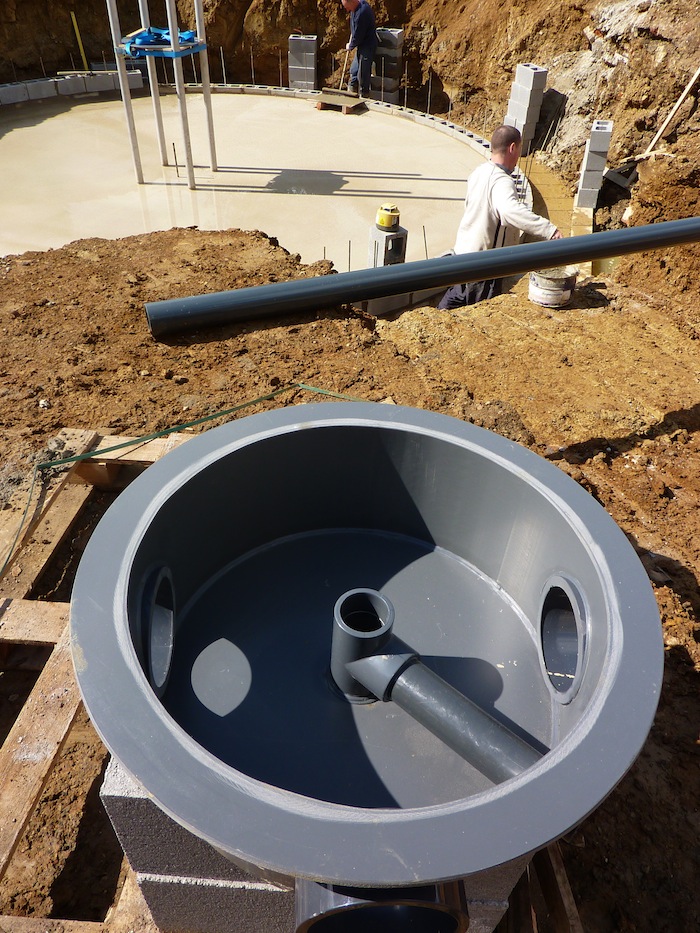
This is the central drain that will supply bottom water to the filtration units; the cigarette pack is there to give an idea of scale.
The sump itself is 18” (45cms) diameter and the top is 35” (90cms) in diameter.
It has three 4” diameter pressure socket off-takes and a 1.5” connection for the air supply to the 12” (30cms) central diffuser.
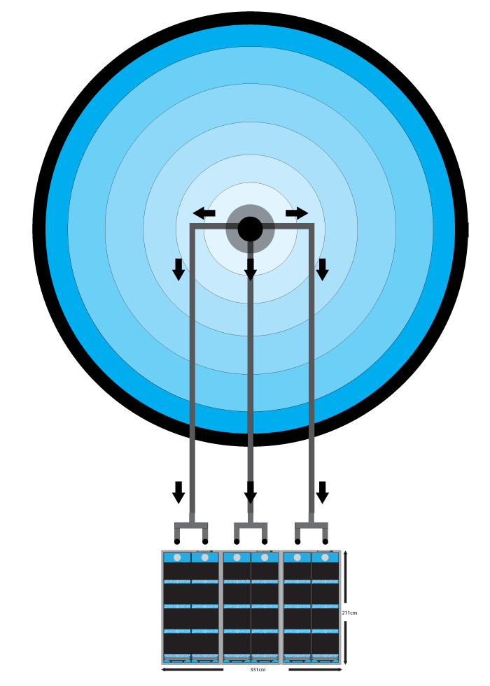
These three 4” lines will exit the pond and be taken some 25 metres away via two 4” 45 degree elbows towards the much shallower filter housing area. Before they enter the area, each line will be split into two lines as shown on this sketch.
As a result the central drain will supply six filter units and still retain the ‘one drain to one filter to one pump’ principle.
I will cover this part of the installation later when progress has been made.
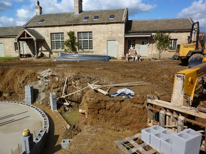
This is a shot taken just before the excavation to the pond area commenced 03/05/10.
As soon as the prime 4” concrete base had been poured it was left to set and the next job was to fix four 3” diameter stainless steel legs to the prime base. This was carried out on 10/05/10 and immediately afterwards a second 4” concrete base was poured to secure these legs after a single course of blocks had been laid to the entire perimeter of the pond.
The four steel legs are longer than required and these will be cut to size once final running water level has been determined. After this, they will be cut to size and a stainless steel table will be welded on top of the legs as a support for the central fountain feature.
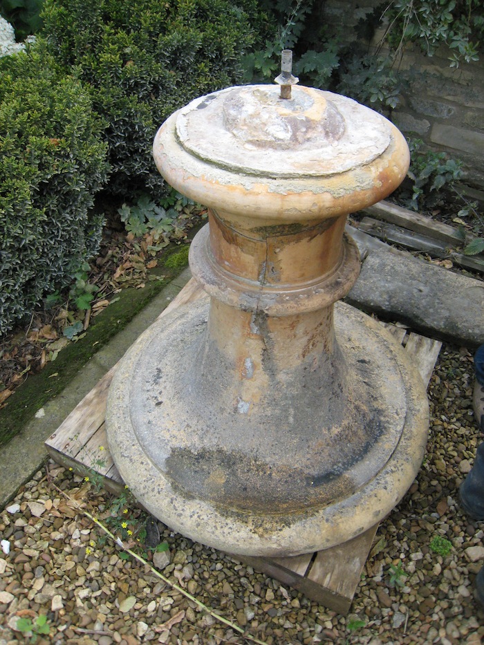
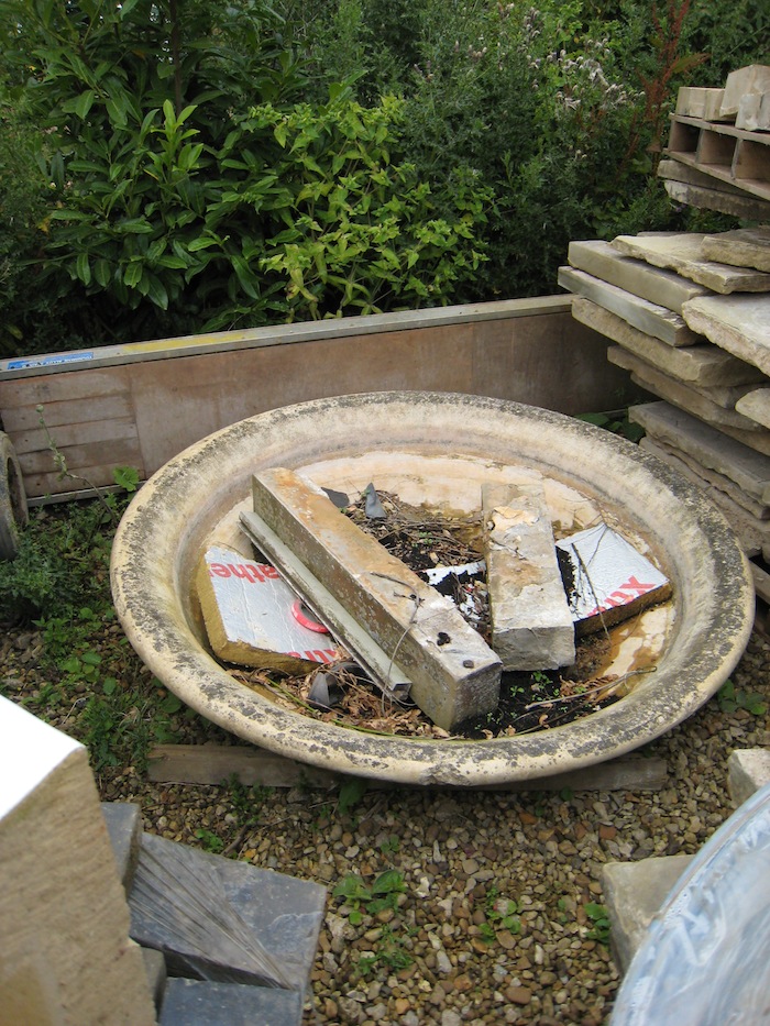
These shots show the base and top bowl of the antique stone fountain that was discovered on an ornamental pond on the estate grounds after purchase of the property.
The combined weight is considerable and so the stainless legs will be filled with concrete as the build progresses.
During the build, these fountain parts will be restored to their former glory. As to the actual material they have been made from, it is suspected to be ironstone, which is commonly found in the surrounding areas.
This was the situation as of 12/05/10 when we went to install the bottom drain and exit pipelines. The initial pipe work and fittings order had arrived ready for use.
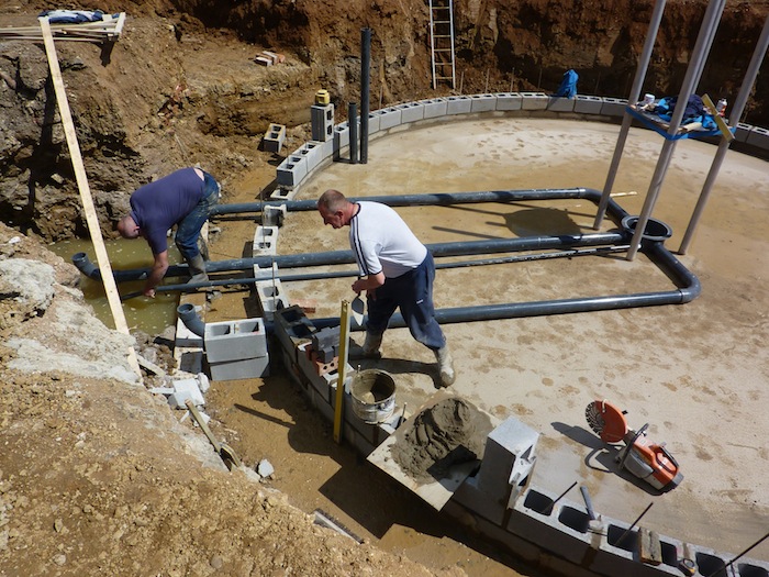
This shows the three 4” drain exit lines and the 1.5” air supply line in place.
There is another 1” diameter blue alkathene line to fix inside one of the steel legs as a concealed water supply to the fountain.
The four lines exiting the pond have had fittings simply pushed into position for removal later. All lines will be secured with mortar and prior to the main 6” base being cast, water will be used to fill these lines in order to ensure no flotation takes place during the pour.
Once the last base has been poured, the pond walls will continue up to 28” (70cms) below final water level and then stop until all the nine 2” bore return lines have been plumbed into place. There are also three pond wall lights to be fitted during the build.

